


HepcoMotion PRT2 – Precision Ring and Track

Chat with us to learn more about this product.
- Request a Quote
- Download CAD File
- Product Info
- Specification
- Success Stories
- Videos
- Faqs
- Reviews
- Low friction motion / zero play
- Extensive range of Ring diameters up to 1501 mm as standard
- Limitless variety of circuits available
- Various carriage plate options
- Stainless steel options
- Simple and effective means of lubrication
- Fully adjustable
- Tolerant of debris
- Tolerant of misalignment and easy to install
- Large hollow center to accommodate other components (ring slides)
- Precision flat surface for mounting ancillary components (ring discs)
- Gearcut options for ease of driving
- High load support option at work station
- Carriage Brake available
- Floating Bearings available - axial movement of vee position
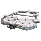
Assembled Rotary Systems
Ring systems are precision ground with hardened V faces for long life. Gear teeth may also be cut along the inner or outer diameter to provide means of actuation. Two types of rotary systems are possible - Rings may be mounted and held stationary with a carriage that moves along the ring, or as a moving object supported by fixed bearing assemblies. Concentric and eccentric bearing assemblies provide smooth and easy motion. The assembled rotary system is an ideal solution for rotary table applications. The rotary table can either be non-actuated, or driven using the geared teeth cut into the ring.
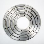
Ring Slides and Segments
Slide rings and segments have hardened 70 degree V faces made from high quality steel. Rings and segments are precision ground with datum register faces - the precise machining allows for easy and accurate installation. Segments are cut from complete rings and stocked in 90 degree and 180 degree segments. Other sizes of segments are available upon request. Double Edge and Single Edge versions available. Gear teeth are available on the inner or outer diameter. Slide rings are ideal for custom rotary tables and medical equipment.
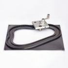
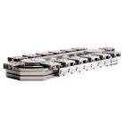
Track Systems
Two types of track - curved segments and straight segments. Track Systems can be combined in a multitude of ways to make customized rotary systems to follow any path. At joints between sections, adjustment keys allow finite positioning of slide segments to each other in order to ensure smooth transitions from one segment to the next.
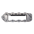
Track System Straight Slides
Straight slides are made from high quality carbon steel with hardened V edges. Mounting surfaces as well as V edges are ground to provide precise and easy installation. Standard lengths are available up to 3956 mm and lengths may be butt-jointed.
Track System Curved Segments
Curved segments are created from standard 90 and 180 degree segments. Each curved segment's ends are ground square in order to mate more easily with adjoining curved segments or straight slides.
Bearing Assemblies
PRT2 bearings are available in a range of 5 useful sizes and various formats to suit most design requirements. All bearings are lubricated for life internally. Available with Metal Shields for exclusion of particulates and low friction running or with Nitrile Seals to inhibit ingress of small particulates liquids. Available in stainless steel fitted with Nitrile Seals. Floating bearings available. Bearing formats include Through-hole fixing type or Blind hole fixing type, and Double Row or Twin type.
To calculate the life of this type of rotary system, first obtain a value for the load factor LF by entering the values for LA, LR, and M in respect to the proposed duty, into the equation below, together with the maximum load capacities from the table above.
Carriage Options
Two types of carriages are available, fixed center carriages and bogie carriages. Fixed center carriages are ideal for rings and segmented tracks. The fixed center carriage design follows track paths from straight to curved sections with ease. The fixed center carriage, however, will not follow "S" type bends, while the bogie carriages will follow any type of curve with smooth and easy motion. Both types of carriages are made from anodized aluminum and can be supplied fully assembled and adjusted to track segments.
The HepcoMotion Fixed Center Carriage with Clamping Brake
Provides a safe and simple method of locking the carriage in position to facilitate processes where a secure, stationary platform is required. The brake is intended for manual locking of a stationary carriage and is available in sizes 25, 44 and 76. The brake contains two opposing jaws which when tightened via the ratchet locking lever, secures the carriage in place. Unlike some other systems the resulting clamping force does not load the bearings or deflect the carriage even when a high force is applied. Due to the position of the brake on the carriage, it is not possible to traverse from a ring segment to a straight slide, therefore these carriages are not suitable for use with track systems and can only be used on ring slides and segments. Click here to download the product page.
Lubricators provide optimal performance of rotary systems by properly lubricating the interface between the V slide and V bearing. A grease reservoir provides continuous lubrication to prolong system life of your rotary table or any other application you may have. Compact type suitable for through hole fixing type bearings. Flanged type for through and blind hole fixing type bearings.
Bleed Lubrication
Suitable for use with Track systems. Lubrication piped through holes, direct into the V contact faces. Controlled metering of lubrication. Overcomes necessity for lubrication service intervals.
- The Static Roller type carriage is designed to take an additional load whilst in a static or stationary position. The carriage is supported when it makes contact with a pair of eccentrically adjustable roller bearings, fitted to the framework of the track system. This set-up provides the system with the extra load capacity needed at a workstation, where large downward forces like punching, pressing or stamping, are often seen.
- The Dynamic Roller type provides continuous support to the carriage, around the entire track whilst the load is moving. In this case, the carriage is fitted with eccentric roller bearings, which can be adjusted to make contact with a support track following the main vee Guide circuit.
Both versions are available in a range of sizes, including an extra wide carriage option. They can be supplied complete with a carriage locking system for positive location within +/- 50 microns and can also be used in straight line linear applications in conjunction with GV3 components.
Sizes to suit all gear cut ring slides, segments and ring discs. Ground teeth for long life and smooth operation on sizes 1 module and above. Hardened teeth on larger sizes for increased durability. All pinions available in stainless steel as option. Precision machined bore with optional keyway.
| Bearing Assembly Size | Used With Ring Part Number | Number of Bearing Assemblies Equally Spaced | Maximum Lubricated | Maximum Unlubricated | ||||
| Load Capacity | Load Capacity | |||||||
| LA (N) | LR(N) | M (Nm) | LA (N) | LR(N) | M (Nm) | |||
| RSJ/BHJ-13 | 3 | 90 | 52 | 18xØc* | 60 | 34 | 13xØc* | |
| R12-93 | 4 | 113 | 60 | 22.5xØc* | 75 | 40 | 16xØc* | |
| R12-127 | Each Additional 1 | 23 | 15 | 4.5xØc* | 5 | 3 | 1.2xØc* | |
| RSJ/BHJ-25 | R25-159 | 3 | 600 | 350 | 150xØc* | 230 | 125 | 55xØc* |
| R25-255 | 4 | 750 | 400 | 187xØc* | 285 | 150 | 69xØc* | |
| R25-351 | Each Additional 1 | 150 | 100 | 37xØc* | 18 | 12 | 5xØc* | |
| RSJ/BHJ-34 | 3 | 1200 | 700 | 300xØc* | 460 | 255 | 110xØc* | |
| R44-468 | 4 | 1500 | 800 | 375xØc* | 575 | 300 | 138xØc* | |
| R44-612 | Each Additional 1 | 300 | 200 | 75xØc* | 38 | 24 | 27xØc* | |
| RSJ/BHJ-54 | 3 | 2850 | 1650 | 750xØc* | 1050 | 600 | 260xØc* | |
| R76-799 | 4 | 3600 | 1900 | 875xØc* | 1300 | 700 | 325xØc* | |
| R76-1033 | Each Additional 1 | 700 | 470 | 175xØc* | 75 | 50 | 18xØc* | |
Carriage Technical Data
| Carriage | Maximum Load Capacity | Maximum Unlubricated Load Cpacity | ||||||||
| Direct Loads (N) | Moment Loads (Nm) | Direct Loads (N) | Moment Loads (Nm) | |||||||
| L1 | L2 | M | MV | MS | L1 | L2 | M | MV | MS | |
| FCP-12-93 | 120 | 120 | 1.25 | 1.25 | 0.6 | 80 | 80 | 0.8 | 0.8 | 0.4 |
| FCP-12-127 | 120 | 120 | 1.2 | 1.2 | 0.6 | 80 | 80 | 0.8 | 0.8 | 0.4 |
| BCP-12 | 120 | 120 | 1.7* | 1.7* | 0.6 | 80 | 80 | 1.2* | 1.2* | 0.4 |
| FCP-25-159 | 800 | 800 | 16 | 16 | 9 | 300 | 300 | 6 | 6 | 3.5 |
| FCP-25-255 | 800 | 800 | 15 | 15 | 9 | 300 | 300 | 6 | 6 | 3.5 |
| FCP-25-351 | 800 | 800 | 17 | 17 | 9 | 300 | 300 | 7 | 7 | 3.5 |
| BCP-25 | 800 | 800 | 27* | 27* | 9 | 300 | 300 | 10* | 10* | 3.5 |
| FCP-44-468 | 1600 | 1600 | 57 | 57 | 35 | 600 | 600 | 22 | 22 | 14 |
| FCP-44-612 | 1600 | 1600 | 65 | 65 | 35 | 600 | 600 | 24 | 24 | 14 |
| BCP-44 | 1600 | 1600 | 75* | 75* | 35 | 600 | 600 | 28* | 28* | 14 |
| FCP-76-799 | 3800 | 3800 | 165 | 165 | 140 | 1400 | 1400 | 62 | 62 | 55 |
| FCP-76-1033 | 3800 | 3800 | 210 | 210 | 140 | 1400 | 1400 | 81 | 81 | 55 |
| BCP-76 | 3800 | 3800 | 220* | 220* | 140 | 1400 | 1400 | 86* | 86* | 55 |
To calculate the life of a rotary system using a standard carriage, first obtain the load factor LF by entering the values for L1, L2, M, MV and MS in respect of the proposed duty into equation [1] below, together with the maximum load capacities from the table above.
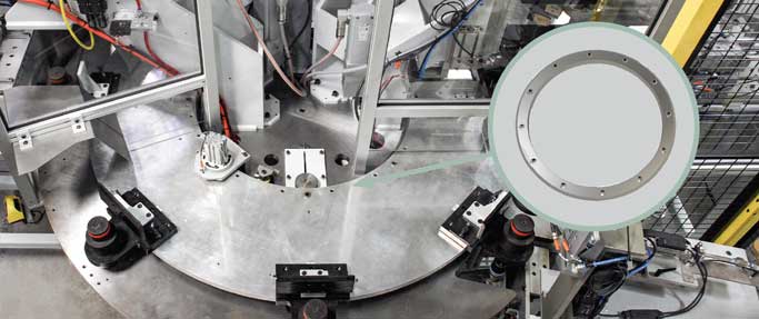
RELIABLE ROTARY INDEXING
High Quality and Low Footprint Dial Press Enables Component Assembly
THE CHALLENGE:
The rotary guidance system for the dials required not only load support, but a large open center. Locating the press frames through the center of the dial would greatly enhance the ease of maintenance, changeover access, and operational visibility of the design. Therefore, it was critical that the rotary system provide a large internal opening to mount the presses.
INDUSTRY: Manufacturing Equipment
PRODUCT USED: HepcoMotion PRT2
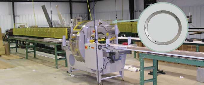
ORBITAL STRETCH WRAPPER
Wrapping System Relies on Vee Guide Technology for Durable Rotary Motion
THE CHALLENGE:
The OEM needed a rotary guided motion system that meets each of the application requirements. The rotary guide solution needed a large open center to accommodate a variety of tunnel diameters (specifically, the 18”, 24” and 40” sizes). However, it also needed a low profile to maximize the space for other elements.
INDUSTRY: Packaging
PRODUCT USED: HepcoMotion PRT2
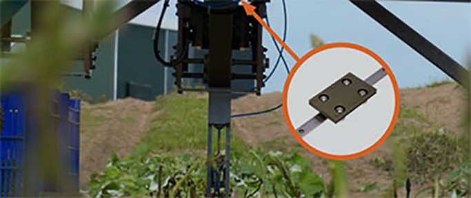
ROBOTIC ASPARAGUS HARVESTER
Multi-Axis Guided Motion for Automation in High Debris Farming Environment
THE CHALLENGE:
Up to this point, asparagus harvesting has largely been an arduous and expensive manual process. The stalks grow at various speeds, so it has been the job of workers to painstakingly cut through each ripe stalk individually. This laborious process makes asparagus one of the most expensive vegetables to produce. With demand on the rise, it has become more important than ever to explore automation solutions to make harvesting sustainable.
INDUSTRY: Agriculture, Food Manufacturing
PRT2 Ring and Track Systems
Animation Demonstrations
Rotary Motion
Moment Load Carriage System